

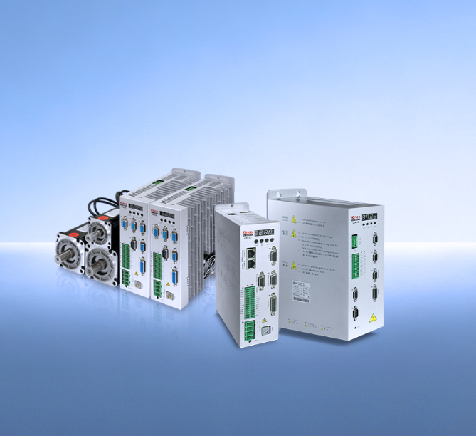
Integrating an AC servo drive is rarely a plug‑and‑play exercise. The process involves multiple subsystems — power, signal, communication, and configuration — and each one can delay the startup if not handled correctly.
A methodical approach reduces troubleshooting time. This guide covers the integration workflow for Kinco JD series AC servo drivers, focusing on the decisions that actually affect whether the system runs on schedule.
What to Confirm Before Mounting the Driver
The integration process starts before any hardware is installed. Confirm that the driver model matches the motor in terms of voltage rating and feedback compatibility. The JD series includes both 220 V AC and 380 V AC input variants, and using an incorrect supply voltage can damage the driver and create a serious commissioning risk.
Check the nameplate on both units. Verify that the encoder cable is the correct type for the feedback interface. Mismatched cables cause position errors that are difficult to diagnose later.
Physical Installation and Power Wiring
Mount the driver inside a control enclosure with adequate airflow around the heat sink. The JD series uses natural convection cooling, so leave clearance above and below the unit. Secure all four mounting points to prevent vibration‑related connection issues over time.
Make the AC supply connections to the main power input terminals and connect the motor phase wires accordingly. Both the motor and driver must be grounded using the dedicated grounding terminal. For signal interfacing, the JD driver provides dedicated ports for serial communication and fieldbus. Use twisted‑pair shielded cables for all communication lines.
Route them in separate cable ducts from the motor power cables, and follow the manufacturer’s recommended separation and grounding practices. Loose terminal connections are a common source of intermittent faults, so torque all terminal screws to the values specified in the installation guide.
Configuration and Commissioning Software
With the hardware installed, connect a PC to the AC servo driver for parameter configuration. Kinco provides the ServoPlus debugging software for this purpose.
Connect the PC to the driver using the RS232 port. Launch ServoPlus and configure the communication parameters — COM port and baud rate must match the driver’s settings. Click the connection test to confirm communication before proceeding.
Once online, the software displays all configurable driver parameters. The critical initial settings involve motor type selection and feedback configuration — these must match the connected motor exactly.
If the motor is not correctly identified in the software, the current loop and encoder decoding will be misaligned, leading to erratic operation that can be mistaken for hardware failure. Getting this part right from the start saves hours of diagnosis later.
Control Mode Selection and Fieldbus Setup
The AC servo driver must receive motion commands from the system controller. The JD series supports multiple command interfaces, and the choice determines how integration proceeds.
Pulse/direction control is the simplest approach for standalone systems. The PLC sends step and direction signals to the driver’s digital inputs, and the driver executes positioning moves accordingly. This requires minimal network configuration.
Fieldbus integration is the preferred method for systems with multiple axes or complex motion coordination. For CANopen integration, import the driver’s EDS file into the PLC programming environment.
Add the JD driver as a slave device on the CAN bus. Set the Node ID and configure the PDO mapping to define how motion data is exchanged with the controller. The driver supports the CiA 402 drive profile, which standardizes motion commands across different hardware platforms.
For systems requiring higher data rates, the JD series also supports EtherCAT connectivity.
Controlled Test Run and Final Verification
Before the system enters production, perform a systematic test run with appropriate safeguards in place. All powered tests should be conducted with proper guarding, emergency‑stop functions active, and safety procedures established.
Test 1 — No‑load verification: With the motor mechanically disconnected from the load, enable the driver and command a low‑speed move. Use the driver’s front‑panel display to verify correct rotation direction and encoder feedback. Check for alarm conditions — the error history in ServoPlus helps identify issues quickly.
Test 2 — Load connection: Once the no‑load test passes, connect the mechanical load. Repeat at low speed and acceleration, then gradually increase both while monitoring torque output and position error. If oscillation or following error occurs, use the software’s tuning function to adjust control loop gains.
Test 3 — Communication validation: Verify that the PLC can command motion over the fieldbus and that status feedback is correctly received. Confirm that alarm handling, status feedback, and emergency‑stop response function as programmed.
Integrating an AC servo driver follows a clear sequence: confirm compatibility, mount and wire correctly, connect the PC for configuration, select the appropriate command interface, and validate with a structured test run. The JD series handles matched Kinco motors with minimal parameter tuning, which reduces commissioning time.
A methodical approach at each stage — particularly in wiring separation and control mode setup — prevents the common errors that extend integration schedules and delay production startups.

